
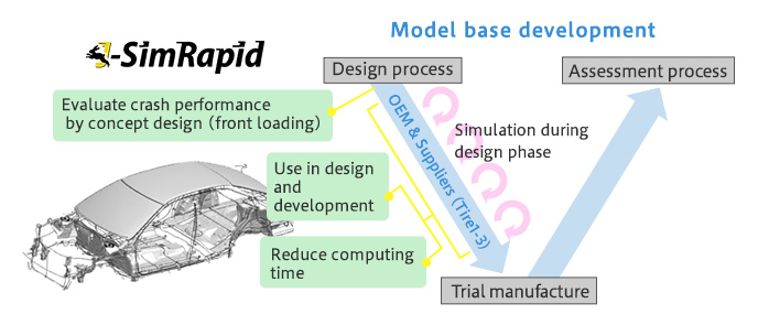
Product development begins with concept design, followed by functional design and detailed design as the design phases progress. As many design changes occur later in the design phase, rework will occur and the development-cost will increase, so front-loading with performance assessment in the first half of the design phase is critical.
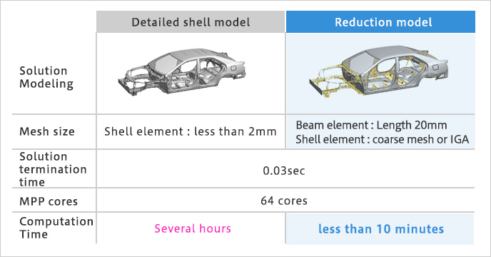
Simplifying analysis models using beam elements has been employed for some time, but it has faced challenges such as limited versatility and difficulty in handling large deformations or collision analysis. To solve this issue, JSOL has developed a beam material model that takes buckling deformation into account (patent pending), and established a new reduction modeling technique that extends the simplification method using beam elements. This allows for impact strength assessment of the device during the initial concept phase of design. In addition, the "Part-specific Reduction Modeling Method (patent-pending)" developed by JSOL realizes a hybrid model that combines a detailed shell-model with a simple beam model. J-SimRapid reduction model supports efficient product-development not only in the early stages, but also during the later phases of functional and detailed design.
In concept design, it is required to examine component shapes and layouts necessary to satisfy product performance in a short time.
The new reduction model offered by J-SimRapid enables the following:
- Lower computing cost
- Easy to change the cross-sectional shape
- Easy to add and remove components
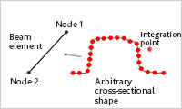
The cross-sectional shape of beams created by J-SimRapid is defined at integration points, so you can change the cross-sectional shape without meshing. With this technology, speedup of the optimization calculation of the cross-sectional shape is realized.
In addition, the "Part-specific reduction modeling method (patent-pending)" developed by JSOL creates a beam model for each part, which facilitates addition and removal of parts.
JSOL Corporation
Create beam models in interactive from Ansys LS-DYNA shell models with dedicated viewers and GUI