

J-Composites Functions
A tool to set up composite material analysis with LS-DYNA
The J-Composites series consists of ”Form Modeler”, a tool to set up press forming analysis, ”Compression Molding”, a tool to set up compression molding analysis, and “Fiber Mapper”, a tool to map the simulated fiber behavior from a resin flow on to a structural mesh .
Press forming simulation modeling tool: Form Modeler
J-Composites / Form Modeler provides three major functions: ”Material DB” creates and manages material data, ”Lay-up Modeler” creates a composite model, and “Lay-up Mapper” maps a fiber result to a structural model.
Based on material test results, J-Composites / Form Modeler automatically identifies the material parameters required for press forming simulation and uses them to create material models. The user-friendly interface enhances the efficiency of creating and managing laminate models.
Form Modeler Main Functionality
-
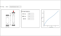
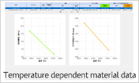
- Material DB: Create and manage material data
- By using Material DB, material test data can be automatically converted into material property parameters for FEM press simulation. The resulting material model enables accurate estimation of the material behavior. With the help of the provided standard material database, users can start simulation right away.
-
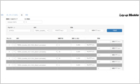
- Lay-up modeler: Define laminates
- By using Lay-up modeler, a press simulation model with a complex laminate construction (no. of plies, fiber angle for each ply) can be created in a few simple steps. Lay-up modeler auto-creates the various definitions needed for each ply in the laminate, including the conditions for contact with the tools, eliminating repetitive and cumbersome manual operations.
-
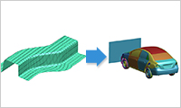
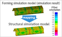
- Lay-up Mapper: Map the resulting fiber direction
- With Lay-up Mapper, the result of the press forming simulation can be used when preparing the subsequent structural analysis. Because fiber-direction governs the behavior of a composite material, a change in fiber direction during forming strongly influences the product’s mechanical properties. By mapping the post-forming fiber direction to a structural mesh, Lay-up Mapper enables structural analysis that accounts for the effects of forming.
Details of J-Composites / Form Modeler
- ・Material DB
-
- - Identify material properties based on test results
- - Save and manage user defined (customized) materials
- - Provides a standard material database
- ・Lay-up Modeler
-
- - Specify the material and the direction of lamination
- - Specify the number of plies in the lay-up and the thickness of each ply
- - Define the contact conditions for simulation in one operation
- - Define the interlaminar friction model
- - Auto-create the simulation model
- - Manage the laminate definition as a template
- ・Lay-up Mapper
-
- - Map the resulting fiber direction
- - Manage the mapping definition as a template
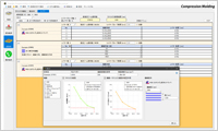
Compression molding simulation modelling tool: Compression Molding
J-Composites / Compression Molding is a tool to support building an LS-DYNA FRP model for compression molding simulation using the beam-in-solid coupling method. You can create a simulation model by reading a shape model, then setting the tools’ forming conditions, the composite material, and the analysis conditions. There is a material database for creating and managing material model data.
Compression Molding Main Functionality
-
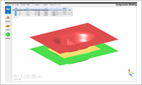
- Shape Model Viewer
- Compression Molding provides a viewer to display the shape model (template model), consisting of the workpiece and tools, during the setup process. The viewer helps in understanding the details of the workpiece and the tools.
-
- Create and manage materials (Material DB)
- Composite materials consist of three types of data: fiber, matrix resin, and fiber-matrix resin interaction. Each data type can be managed in the database and new composite materials created by combining them.
-
- Fiber model (beam elements) generation
- A fiber model (beam elements) can be generated by inputting parameters such as fiber composition type (ROS, ROF, UD, CUD), fiber length, strand size, number of layers, and layer pattern, etc. The estimated number of beam elements to be generated can be checked in advance.
Compression Molding Features
- ・Material DB
-
- - Create and manage materials
- - Import and export material data
- ・Geometry
-
- - Import template model (workpiece and tool geometry data)
- - Compatible with arbitrary shape matrix resin
- ・Forming condition
-
- - Specify each tool’s moving direction and displacement
- - Animated display of tool movement
- ・Workpiece
-
- - Specify fiber composition type (ROS, ROF, UD, CUD)
- - Specify strand size (ROS), fiber length (ROF, CUD), cut angle (CUD)
- - Specify forming temperature
- - Specify number of layers (ROS, ROF), layer pattern (UD, CUD)
- - Generate fiber model (beam elements)
- - Generate matrix resin model (tetrahedral solid elements)
- ・Analysis condition
-
- - Define analysis conditions depending on test method (compression molding, squeeze flow)
- - Molding phase switching setup depending on the distance between tools
- - Automatic setup of control cards and contact definition optimized for stable calculation
- - Save project data
- - Adjust uncoupled fiber model deletion
- - Apply mass scaling to all elements (optional)
- ・Other
-
- - Help function
- - Available in Japanese and English
Resin flow simulation model mapping tool: Fiber Mapper
J-Composites / Fiber Mapper provides an interface function which connects LS-DYNA and the forming simulation result. Connecting these enables structural simulation accounting for the forming simulation result for discontinuous fiber reinforced plastic (process chain simulation).
Fiber Mapper can map the forming simulation result on to the structural mesh and create a material model input, making it easy to create process-chain simulation models.
Fiber Mapper Main Functionality
-
- Map the forming simulation result
- Fiber Mapper appropriately maps the fiber orientation data obtained from a forming simulation on to a structural mesh. The mapping scope can be limited by part. Parallel processing is taken advantage of when possible to help map large models smoothly.
-
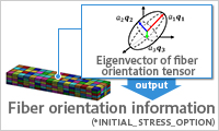
- Ease complex and difficult composite material model creation
- The fiber orientation data from a forming simulation can be automatically converted into a material model input. Eliminates time-consuming repetitive operations.
Details of Fiber Mapper
- - Map fiber orientation data on to a structural mesh
- - Select the mapping scope
- - Modify the mapping search tolerance
- - Convert fiber orientation data
- - Manage the mapping definition as a template
- - Parallel processing
- - Supported UI Languages: Japanese / English
Supported platforms
| OS |
|
|---|---|
| Display resolution | 1920 x 1080, 1920 x 1200 recommended (Minimum 1024 x 720) |
| Graphics card | Must support OpenGL 4.3 or higher (Compression Molding only) |
| License types | Node locked and floating license available |
- *Some models posted on this site are provided by NCAC/GWU.
- *Product names and service names are the trademarks or the registered trademarks of their proprietors.