JSTAMP
JSTAMP
CAE application to springback
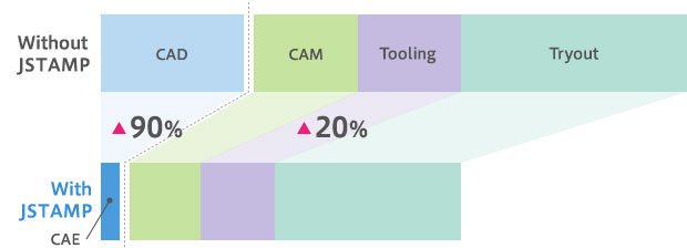
- JSTAMP achieves one-tenth of conventional man-hours
- Applied to production die manufacturing for body thin-sheet parts
An anonymous mold manufacturing company located in Kanagawa prefecture, Japan, started to use JSTAMP/NV in 2003 to respond to customers' QCD needs.
The main target is the tool for mass-production of sheets measuring less than 1 mm in thickness.
Motivation
They received an inquiry from a foreign company which had a simulation being conditional on the order, nearly a decade ago. Simulation is now conditional on orders for inquiries from domestic companies.
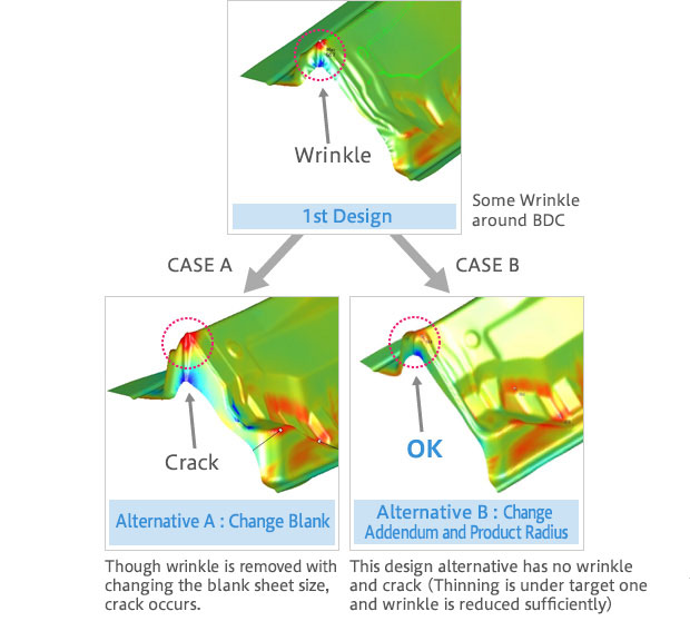
They applied CAE to predict cracks and wrinkles on a drawing tool (see fig. 1). For springback prediction, they asked their parent company owing to limitations in terms of performable load and computation time.
Operational framework
Four operators who understand 3D-CAM operate all CAM/CAE works for eight parts per a month. They started the operation after attending training seminars at JSOL followed by a few months of training. They upgraded to a "PC-type" system, and the UI of this version of JSTAMP is much more user-friendly than the previous "UNIX-type" ones.
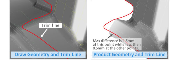
For domestic order parts, they must regulate until the simulated thickness reduction rate falls within the range specified by the customer. Sometimes, this process requires them to build more than ten trial models and perform the same number of simulation runs. There is also the case that the customer does not allow the manufacturer to create CAM data until the thickness reduction rate falls within the specified range. In terms of the trim line development feature, JSTAMP is quicker and more accurate than the CAD development, which leaves a gap of a few mm. [Fig. 2]
Achievement
Applying CAE reduced the workload to 1/10th of the original and improved the accuracy up to a gap of +/-1.0 mm. The loss of workload in the tool manufacturing process was reduced dramatically. [Fig. 3]